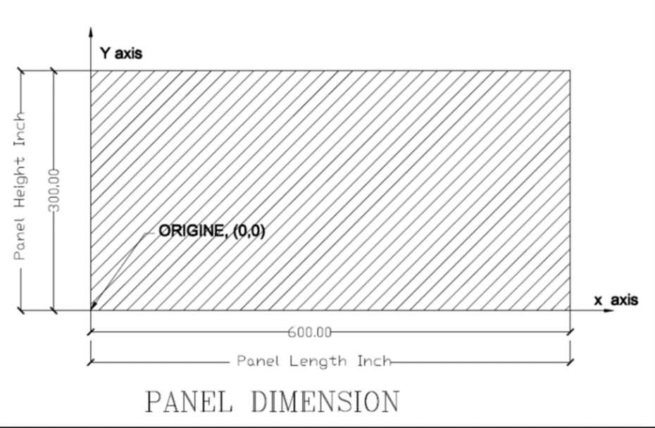
Panel Dimensions
Wall Panels input dimensions are located in three locations in the input sheet data:
- Length and height of the panel.
- Top track slope numbers and locations
Top Track Input Data
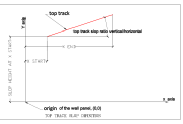
Input Data for Flat or Sloped Top Tracks:
FrameProX offers the flexibility to create and cost-estimate wall panels featuring either flat or multiple sloped top tracks. To accurately model these features, please input the following information for each slope:
- Number of Slopes: Specify the total number of slopes within the top track.
- Slope Coordinates:
- X Start: Enter the X-axis coordinate marking the beginning of each slope.
- X End: Enter the X-axis coordinate marking the end of each slope.
- Height at Slope Start: Provide the vertical height at the beginning of each slope (at the X Start coordinate). This value requires manual calculation, as explained below.
- Slope Value: Indicate the gradient or angle of each slope.
Manual Height Calculation:To determine the height at the start of a slope, follow these steps:
- Identify the Reference Height: Establish a known height reference point, such as the top of a wall panel or a specific elevation.
- Calculate the Vertical Distance: Measure the vertical distance between the reference point and the point where the slope begins (at the X Start coordinate).
- Subtract from Reference Height: Subtract this vertical distance from the reference height to obtain the final height value for slope input.
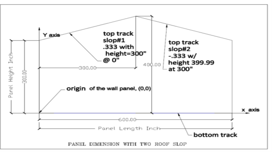
Graphical Representation:The diagram below visually illustrates the required input parameters for each slope:
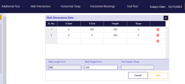
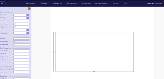
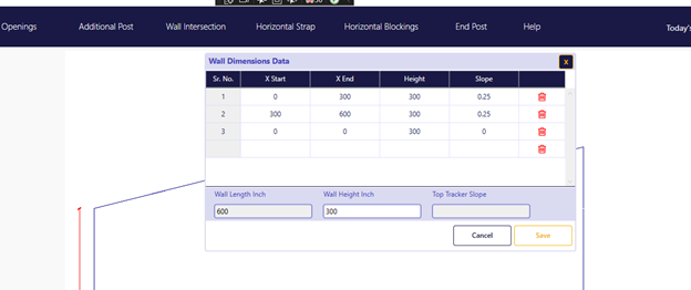
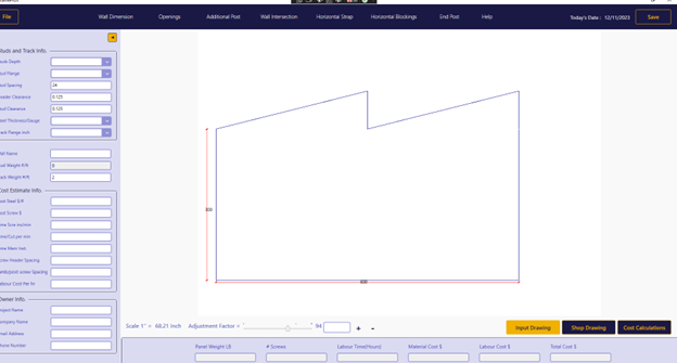
Example 1 - Case for Flat Top Track:
For a wall panel with a flat top track, like the one illustrated below, follow these input steps:
- Number of Slopes: Enter 1, as there's only one flat segment.
- Slope Coordinates:
- X Start: 0 (beginning of the top track)
- X End: 600 (end of the top track)
- Height at Slope Start: 300 (assuming a reference height of 300 at the beginning of the top track)
- Slope Value: 0 (indicating a flat top track)
Remember:
- For multiple slopes, repeat the input process for each individual slope, providing its respective coordinates and height values.
- Consult the FrameProX Help Center or contact our support team for further assistance.

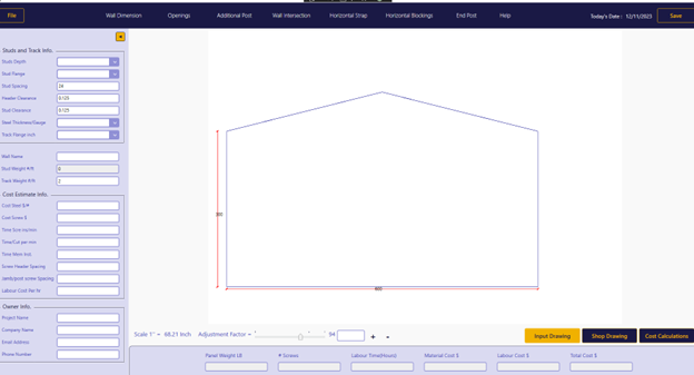
Example 2: Top Track with Two Slopes:For a wall panel with two slopes in the top track, one sloping upward and the other downward, as shown below, follow these input steps:Slope 1:
- Number of Slopes: 2 (as there are two separate slopes)
- Slope Coordinates:
- X Start: 0 (beginning of the top track)
- X End: 300 (end of the first slope)
- Height at Slope Start: 300 (assuming a reference height of 300 at the beginning)
- Slope Value: 0.333 (positive value indicating an upward slope)
Slope 2:
- Slope Coordinates:
- X Start: 300 (beginning of the second slope)
- X End: 600 (end of the top track)
- Height at Slope Start: 400 (height at the beginning of the second slope)
- Slope Value: -0.33 (negative value indicating a downward slope)
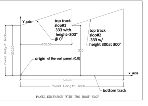
Example 3: Top Track with Two Upward Slopes:
Slope 1:
- Number of Slopes: 2 (as there are two separate slopes)
- Slope Coordinates:
- X Start: 0 (beginning of the top track)
- X End: 300 (end of the first slope)
- Height at Slope Start: 300 (assuming a reference height of 300 at the beginning)
- Slope Value: 0.333 (positive value indicating an upward slope)
Slope 2:
- Slope Coordinates:
- X Start: 300 (beginning of the second slope)
- X End: 600 (end of the top track)
- Height at Slope Start: 300 (height at the beginning of the second slope, as it starts from the same reference height)
- Slope Value: 0.33 (positive value indicating another upward slope)
- Slope Coordinates:
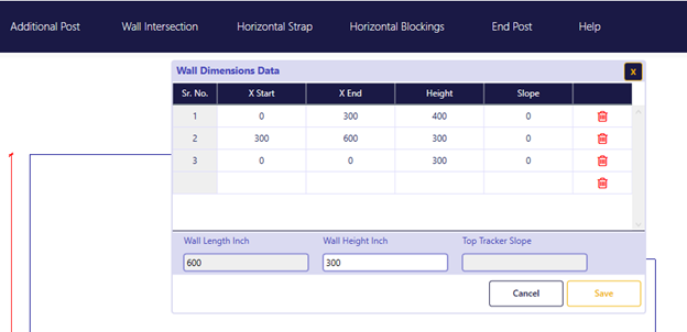
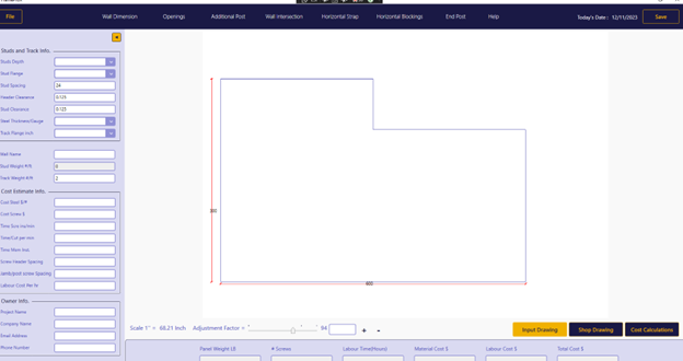
In this scenario, we'll guide you through modeling a wall panel composed of two flat top tracks, each positioned at a distinct elevation.Input Steps:Number of Slopes: Add 2 to indicate the two separate flat tracks.Slope 1:
- Slope Coordinates:
- X Start: 0 (beginning of the first track)
- X End: 300 (end of the first track)
- Height at Slope Start: 400 (height of the first track's starting point)
- Slope Value: 0 (representing a flat track)
- Slope Coordinates:
Slope 2:
- Slope Coordinates:
- X Start: 300 (beginning of the second track)
- X End: 600 (end of the second track)
- Height at Slope Start: 300 (height of the second track's starting point)
- Slope Value: 0 (representing a flat track)
- Slope Coordinates:
Key Points:
- Ensure precise input of coordinates and height values to guarantee accurate shop drawings and cost estimates.
- Double-check all measurements for optimal results.
- If available, consult a visual representation of the wall panel to verify the input values align with the design.
Defining Openings
Welcome to Section 3, where we'll guide you through accurately defining openings within your wall panel design. This includes doors, windows, and any other rectangular wall openings.
Key Input Parameters:
- Shape: FrameProX currently supports rectangular openings.
- Maximum Number: You can create up to 16 openings per wall panel.
- Essential Information: For each opening, provide the following:
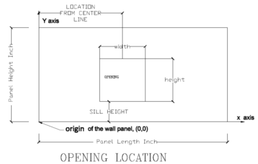
- Location: Indicate the horizontal center of the opening relative to the wall panel's origin (0, 0).
- Sill Height: Specify the height from the floor to the bottom of the opening.
- Width: Enter the overall width of the opening.
- Height: Enter the overall height of the opening.
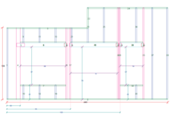
An Example with One Door and Two Windows:This section demonstrates how to define openings in FrameProX using a specific example: a wall panel with one door and two windows.
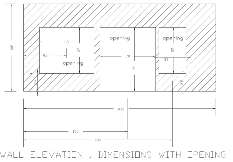
Wall panel dimensions taken from the architectural drawings.
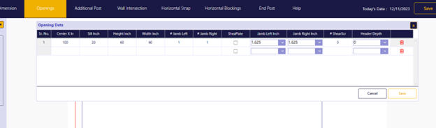
Number of Openings: Add 3 rows in the designated table to indicate the one door and two windows.
Opening Location: Specify the center point of each door or window's opening relative to the wall panel's origin (0, 0). In this example:
- Center of Opening 1 (from left): 54 inches.
- Center of Opening 2 (from left): 130 inches.
- Center of Opening 3 (from left): 130 inches.
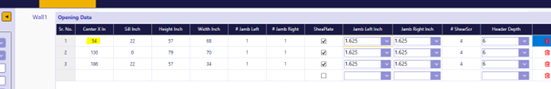
The center line for the second opening starting from the left is 130 inch.
The center line for the second opening starting from the left is 130 inch.
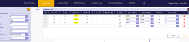
Sill Height: Enter the height from the floor to the bottom of each door or window. See diagram for visual reference:
- Sill Height of Opening 1: 22 inches.
- Sill Height of Opening 2: 0 inch.
- Sill Height of Opening 3: 22 inches.
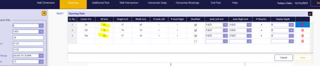
Picture for sill height input for the openings
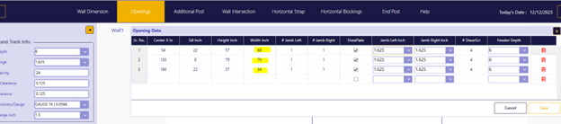
Opening Height: Input the overall height of each door or window:
- Height of Opening 1: 57 inches.
- Height of Opening 2: 79 inches.
- Height of Opening 3: 57 inches.
Picture for the height input for each openings
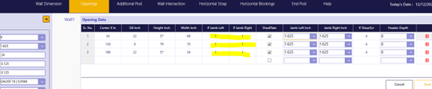
Opening Width: Indicate the total width of each door or window:
- Width of Opening 1: 68 inches.
- Width of Opening 2: 70 inches.
- Width of Opening 3: 34 inches.
Picture for the width input for each openings
- Number of Jambs: For this version of FrameProX - Always set the number of jambs (structural elements) on each side (left and right) of an opening to 1. This can be a single stud or a composite section.
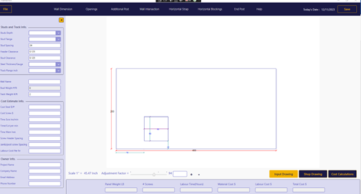
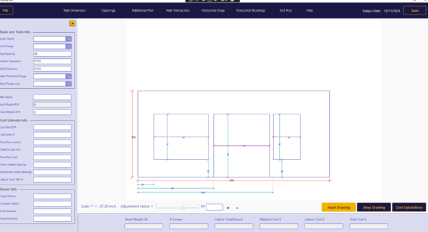
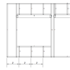
Generating the Drawing:
- After accurately inputting all data, run the program to create a visual representation of the wall panel. This drawing will precisely depict the location, size, and jamb configuration of each door or window.
Remember: This example serves as a guide. Adjust the information according to your specific wall panel design and door configurations.
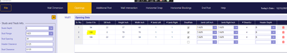
Shear Plate Connections for Enhanced Structural Integrity:
FrameProX provides the option to incorporate shear plates between headers and jambs, ensuring a robust load transfer mechanism within wall panel openings. These plates are installed on both sides of the header-jamb junction, effectively distributing vertical loads.
Key Input Parameters:
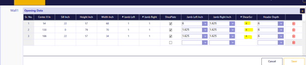
- Enabling Shear Plates: For each opening, activate the shear plate option by checking the corresponding box within the software.
- Number of Screws: Specify the number of screws per side for each shear plate connection. This value applies to both the header and jamb sides. In the example provided, 4 screws per side are used, resulting in a total of 8 screws per shear plate. Refer to the highlighted section in yellow within the software for visual guidance.
Header Configuration:
- Header Size: Define the depth of the header using the drop-down menu, ranging from 0 (no header) to a 12-inch deep header.
- Header Structure: FrameProX models headers as box sections composed of two studs and two tracks. Input the appropriate header depth for accurate representation.
Output Shop Drawings: After completing all input parameters, accurately model wall panel openings with shear plate connections, generating precise shop drawings that reflect the structural details.
FrameProX give the user the option to have shear plate connections between the Header and the Jamb. The shear plate is to transfer the vertical load from the header to the Jamb. The shear will be installed on both sided of the header and the jamb. As shown in the picture below for each opening by checking to have a shear plate.
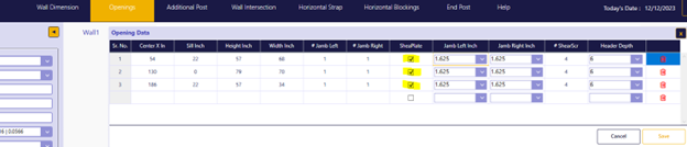
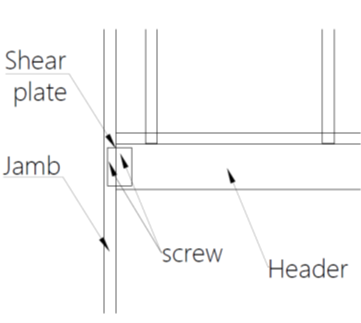
Picture for shear plate per side to connect the Header to the jamb
Input the number of screw
Header Configuration:
- Header Size: Define the depth of the header using the drop-down menu, ranging from 0 (no header) to a 12-inch deep header.
- Header Structure: FrameProX models headers as box sections composed of two studs and two tracks. Input the appropriate header depth for accurate representation.
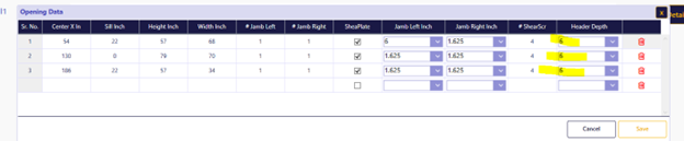
Input header depth.
Output Shop Drawings: After completing all input parameters, accurately model wall panel openings with shear plate connections, generating precise shop drawings that reflect the structural details.
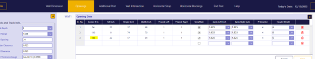
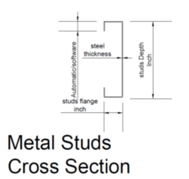
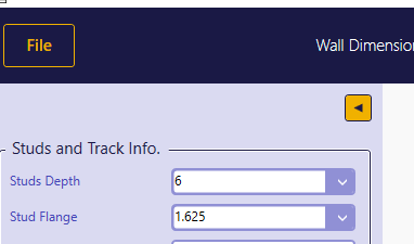
Specifying Metal Stud Details
FrameProX empowers you to define precise metal stud characteristics for accurate model creation and cost estimation.
Key Input Parameters:
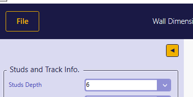
- Depth: Select the desired stud depth from a range of 2.5 inches to 12 inches using the convenient drop-down menu. All dimensions are in inches.
- Flange: Choose the appropriate stud flange width, ranging from 1 inch to 4 inches, using the provided drop-down menu.
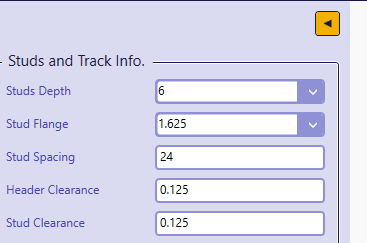
- Spacing: Define the desired spacing between studs. FrameProX accommodates a wide range of spacing values to match your project requirements.
- Minimum Spacing: The spacing cannot be less than the flange width of the studs to ensure structural integrity and proper assembly.
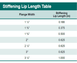
- Lip Dimension: FrameProX adheres to AISI code-compliant lip dimensions for accuracy and consistency.
Remember:
- Consult your architectural drawings or project specifications for the exact stud dimensions needed for your design.
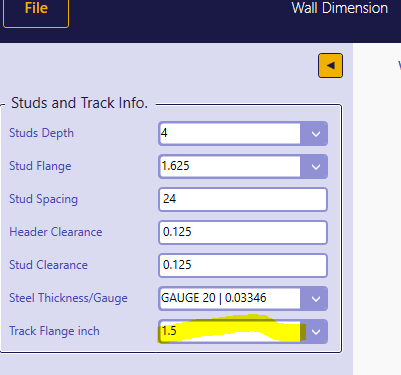
Defining Metal Track Specifications
FrameProX streamlines the track input process by automatically aligning track depth with the previously specified stud depth. This ensures consistency and accuracy within your model.Key Input Parameter:
- Flange: The only input required for tracks is the flange width. Select the appropriate flange size from a range of 1.25 inches to 4 inches using the drop-down menu.
Track Details:
- Depth: As mentioned, the track depth automatically matches the input stud depth.
- Steel Thickness: The track steel thickness mirrors the steel thickness previously defined for the studs.
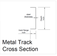
Remember: FrameProX assumes consistent stud and track depths for structural integrity and efficient framing practices.
Personalizing Your Wall Panel with a Name
FrameProX offers the flexibility to assign a unique name to each wall panel, facilitating organization and clarity within your project.
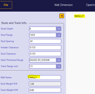
- Locate the designated field for wall name input within the software.
- Enter a descriptive name that effectively identifies the panel.
- The panel name will be visible on the screen alongside the generated model.
- Improved Organization: Easily distinguish and manage multiple wall panels within your project.
- Enhanced Clarity: Effortlessly reference specific panels during communication and collaboration with team members.
- Streamlined Management: Track progress and identify potential issues more efficiently.
- Choose names that clearly convey the panel's purpose or location within the project.
- Use consistent naming conventions for a well-organized project structure.
Calculating Material Weight per Linear Foot
- Stud depth
- Stud flange width
- Track flange width
- Steel thickness
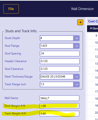
- Stud Weight per LF: View the weight of a single stud per linear foot, factoring in its dimensions and material properties.
- Track Weight per LF: Access the weight of a single track per linear foot, based on its specified flange width and steel thickness.
- Accurate Material Estimation: Precisely determine the overall weight of studs and tracks required for your project, ensuring efficient material ordering and budgeting.
- Cost Optimization: Make informed decisions regarding material choices and quantities to align with project budget constraints.
- Material Handling Efficiency: Anticipate transportation and handling requirements based on accurate weight calculations.
Generating Accurate Cost Estimates
FrameProX extends its capabilities beyond modeling and shop drawings to provide a comprehensive cost estimation tool. This feature empowers informed decision-making and budget optimization throughout the design process.
Key Input Parameters:
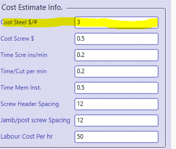
Cost of steel ($/pound)
Input the current cost of steel per pound to accurately reflect material expenses.
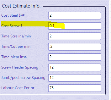
Screw cost
Indicate the cost of individual screws to account for their financial impact.
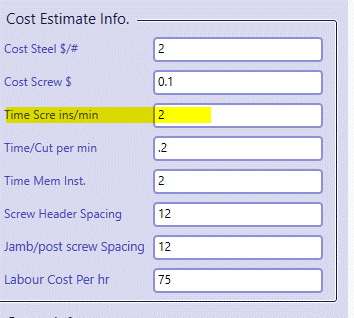
Average Time to Install Each Screw (minutes)
Specify the average time required to install a single screw, ensuring accurate labor cost calculations.
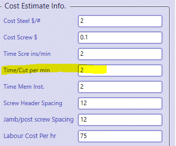
Average Time to Cut a Member (minutes)
Input the average time needed to cut a single member, accounting for cutting labor costs if applicable.
Average Time to Install One Member (minutes)
Define the average time required to install a single member, ensuring precise labor cost estimates.
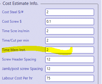
Labor Cost per Hour
Specify the hourly labor cost to calculate overall labor expenses for various tasks.

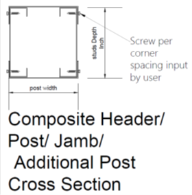
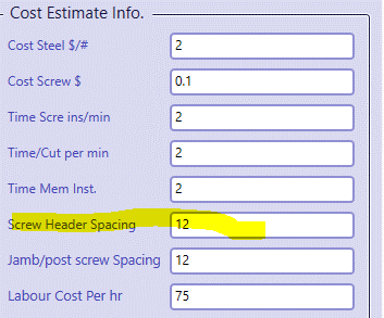
Screwing Spacing for Headers
Input the spacing between screws for header connections, as headers are modeled as box sections.
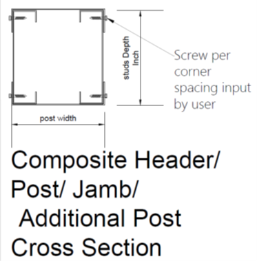
Screwing Spacing for Posts/Jambs/Additional Posts/End Posts
Indicate the spacing between screws for these elements, also modeled as box sections.
Comprehensive Cost Breakdown: FrameProX leverages these input parameters to generate a detailed cost estimate, encompassing:
Material Costs:
- Cost of studs based on length and weight
- Cost of tracks based on length and weight
- Cost of screws based on quantity
- Cost of screw installation
- Cost of member cutting (if applicable)
- Cost of member installation
- Time required for all assembly tasks
- Project Budgeting: Accurately forecast project expenses to ensure financial feasibility.
- Material Optimization: Make informed choices about materials and quantities to reduce costs without compromising quality.
- Labor Efficiency: Identify potential time-saving measures or labor allocation strategies to streamline production and reduce labor costs.
- Value Engineering: Explore alternative designs or material choices to achieve cost savings while maintaining structural integrity.
- FrameProX assumes consistent labor productivity rates for calculations.
- Consult current market rates for steel and labor costs for most accurate estimates.
Comprehensive Cost Breakdown: FrameProX leverages these input parameters to generate a detailed cost estimate, encompassing:Material Costs:
- Cost of studs based on length and weight
- Cost of tracks based on length and weight
- Cost of screws based on quantity
Labor Costs:
- Cost of screw installation
- Cost of member cutting (if applicable)
- Cost of member installation
Total Fabrication Time:
- Time required for all assembly tasks
Benefits of Cost Estimation:
- Project Budgeting: Accurately forecast project expenses to ensure financial feasibility.
- Material Optimization: Make informed choices about materials and quantities to reduce costs without compromising quality.
- Labor Efficiency: Identify potential time-saving measures or labor allocation strategies to streamline production and reduce labor costs.
- Value Engineering: Explore alternative designs or material choices to achieve cost savings while maintaining structural integrity.
Remember:
- FrameProX assumes consistent labor productivity rates for calculations.
- Consult current market rates for steel and labor costs for most accurate estimates.
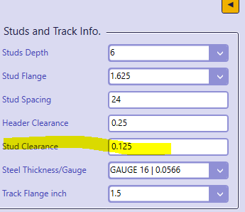
Refining Accuracy with Clearance Adjustments
FrameProX empowers you to fine-tune the fit of framing elements within your model by adjusting clearance distances between specific components. This ensures precise model accuracy and aligns with common construction practices.Key Adjustments:
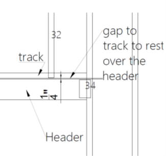
- Clearance Between Header Top and Track:
- Input the desired distance between the top of a box beam header and the bottom of the track directly above it.
- Selectable range: 0 to 0.25 inches
- Purpose: Accommodate potential installation tolerances or specific design requirements.
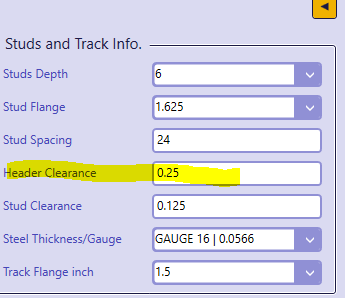
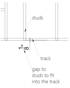
- Clearance Between Stud Ends and Tracks:
- Define the gap between the ends of studs and the tracks they fit into.
- Recommended value: 1/8 inch (common practice)
- Purpose: Account for the track's steel thickness and ensure a snug fit without overstressing the studs during installation.
Importance of Clearance Adjustments:
- Accurate Model Representation: Reflect real-world construction practices and create accurate shop drawings for fabrication and assembly.
- Installation Tolerances: Account for minor variations in material dimensions or installation conditions to prevent potential fit issues.
- Structural Integrity: Ensure proper load transfer and prevent excessive stress on connections by allowing for appropriate clearances.
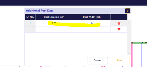
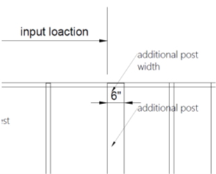
Tailoring Wall Panel Strength with Additional Posts
FrameProX provides the flexibility to incorporate additional posts beyond those automatically generated for wall openings. This feature caters to specific structural requirements or design preferences.Key Input Parameters:
- Post Location Inch: Accurately define the desired location of each additional post relative to the wall panel's origin (0, 0).
- Post Width Inch: Specify the width of each additional post to ensure alignment with structural needs and design intent.
Software Integration:
- Shop Drawing Incorporation: FrameProX seamlessly integrates additional posts into the generated shop drawings, providing clear visual representation for fabrication and assembly.
- Cost Estimation: The software automatically calculates the cost of adding these posts, factoring in material and labor expenses, ensuring comprehensive cost awareness.
Benefits of Additional Posts:
- Enhanced Structural Capacity: Reinforce wall panels for increased load-bearing capabilities or to meet specific design requirements.
- Design Flexibility: Accommodate unique architectural features or support elements within the wall panel.
- Project Specificity: Tailor wall framing to precise structural needs, ensuring optimal performance and safety.
Remember: Consult structural drawings or engineering specifications for guidance on the location and dimensions of additional posts.
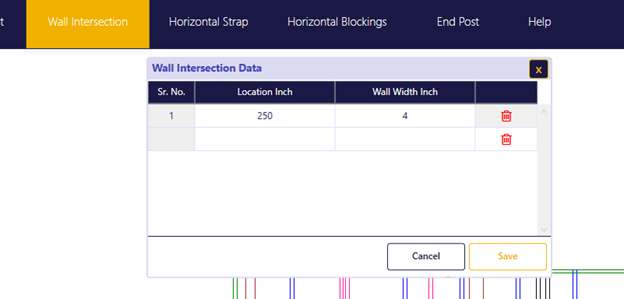
Ensuring Wall Intersection Integrity with Backing Studs
FrameProX meticulously handles wall intersections, automatically adding backing studs to provide a robust structural foundation for drywall installation. This feature ensures seamless transitions between intersecting walls and prevents potential structural or aesthetic issues.Key Input Parameters:
- Location Inch: Indicate the precise location of the intersecting wall relative to the primary wall panel's origin (0, 0).
- Wall Width Inch: Specify the width of the intersecting wall to determine the extent of backing stud placement.
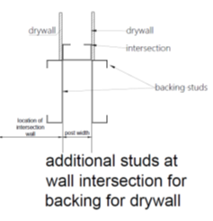
Software Actions:
- Automatic Backing Stud Placement: FrameProX strategically inserts two additional studs at the intersection, providing adequate support for drywall across both wall surfaces.
- Shop Drawing Integration: These backing studs are accurately reflected in the generated shop drawings, guiding precise fabrication and assembly.
Benefits of Backing Studs:
- Structural Reinforcement: Enhance the strength and stability of the wall assembly at intersections, preventing potential cracks or damage.
- Drywall Support: Create a secure and even surface for drywall installation, ensuring a smooth and professional finish.
- Seamless Transitions: Facilitate a visually cohesive appearance where walls meet, minimizing aesthetic irregularities.
Remember: Consult architectural drawings or project specifications for accurate details regarding intersecting wall locations and dimensions.
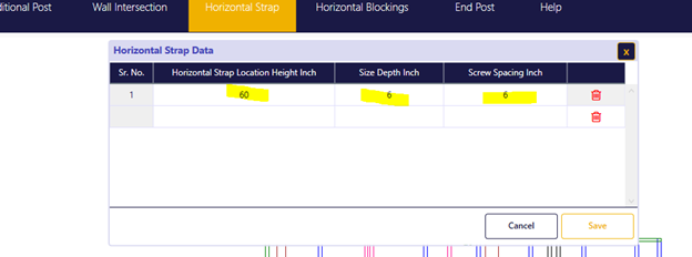
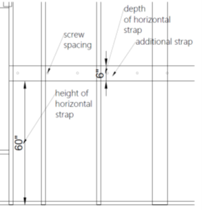
Enhancing Structural Rigidity with Horizontal Strapping
FrameProX offers the option to incorporate horizontal strapping within your wall panels for additional structural reinforcement, particularly in situations where light-gauge steel framing is used.Key Input Parameters:
- Horizontal Strap Location Height Inch: Define the desired height at which the strap will be placed within the wall panel.
- Size Depth Inch: Specify the depth of the horizontal strap to match your structural requirements.
Software Functionality:
- Visual Representation: FrameProX accurately depicts the location and dimensions of the strap within the generated shop drawings, ensuring clear communication for fabrication and assembly.
- Cost Calculation: The software automatically calculates the material and labor costs associated with adding the strap, providing comprehensive project cost insights.
Benefits of Horizontal Strapping:
- Increased Load-Bearing Capacity: Enhance the wall panel's ability to withstand horizontal loads and prevent potential deformation.
- Stiffness Enhancement: Improve the overall rigidity and stability of the wall, particularly for taller or wider panels.
- Code Compliance: Facilitate compliance with building codes or specific project requirements that mandate horizontal strapping for certain wall configurations.
Remember: Consult structural drawings or engineering specifications to determine if horizontal strapping is necessary for your project and to define the appropriate location and depth. The FrameProX Help Center or support team can assist with any questions regarding strapping calculations, code compliance, or cost implications.
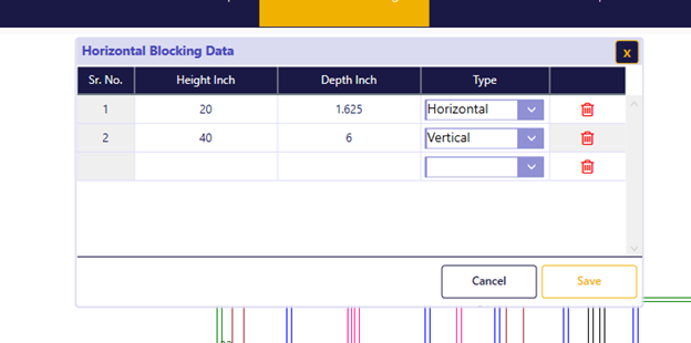
Enhancing Strength and Stability with Horizontal/Vertical Blocking
FrameProX empowers you to strategically incorporate both horizontal and vertical blocking within your wall panels, significantly enhancing structural integrity, stiffness, and support for various fixtures.Key Input Parameters:
- Location (height/depth): Precisely define the intended position of each horizontal or vertical block within the wall panel, ensuring accurate placement for intended functions.
- Dimensions:
- Horizontal Blocking: Automatically aligns with the flange width of the studs, fitting snugly between them for seamless integration.
- Vertical Blocking: Matches the depth of the studs and is installed on the exterior face, requiring flange trimming for a flush fit.
Software Integration:
- Shop Drawing Representation: FrameProX meticulously integrates blocking elements into the generated shop drawings, providing clear visual guidance for fabrication and assembly.
- Cost Estimation: The software automatically factors in the material and labor costs associated with adding blocking, ensuring comprehensive project cost visibility.
Purposes of Blocking:
- Structural Reinforcement:
- Bolster wall strength and load-bearing capacity around openings (doors, windows) or at concentrated load points.
- Enhance overall stiffness and stability against lateral loads.
- Fixture Support:
- Securely anchor heavy fixtures or cabinets to the wall framing.
- Provide backing for electrical boxes, plumbing fixtures, or other utility installations.
- Fire Blocking:
- In some cases, strategically placed blocking can serve as a fire barrier, impeding the spread of flames within wall cavities.
Remember: Consult structural drawings or engineering specifications for specific blocking requirements and locations.
Additional Considerations:
- Flange Trimming: Emphasize the necessity of trimming stud flanges to accommodate vertical blocking installation, ensuring a flush fit and a smooth wall surface.
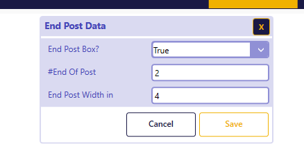
Bolstering Shear Wall Performance with End Posts
FrameProX caters to the unique structural demands of shear walls by enabling the incorporation of end posts. These posts act as robust anchors at the wall's extremities, significantly enhancing its ability to withstand lateral forces and resist deformation.Key Input Parameters:
- End Post Width (inches): Specify the desired width of each end post, ensuring it aligns with structural requirements and load-bearing needs.
- Number of End Posts: Indicate the quantity of end posts required for each end of the wall panel, typically one or two depending on the wall's length and design.
Software Features:
- Box Section Construction: FrameProX automatically models end posts as box sections, offering superior strength and stability compared to single-stud construction.
- Shop Drawing Incorporation: End posts are accurately represented in the generated shop drawings, providing clear guidance for fabrication and assembly.
- Cost Estimation: The software seamlessly factors in the material and labor costs associated with end posts, ensuring comprehensive project cost visibility.
Benefits of End Posts in Shear Walls:
- Enhanced Lateral Load Resistance: End posts significantly bolster the wall's ability to withstand horizontal forces such as wind or seismic activity, preventing potential damage or collapse.
- Improved Structural Integrity: They contribute to the overall strength and stiffness of the shear wall system, ensuring optimal performance under load.
- Load Distribution: End posts effectively distribute lateral loads across the entire wall panel, reducing stress concentrations and minimizing potential failure points.
Remember: Consult structural drawings or engineering specifications to determine the exact width, number, and placement of end posts required for your shear wall design.